
- 01-04-25BIT as a Service
- 26-03-25Internetproviders verliezen rechtszaak over blokkeren websites
- 19-02-25BIT introduceert server-side e-mailfiltering met Sieve
- 06-02-25Shared hosting wordt opgefrist
- 28-11-24ECOFED uitgeroepen tot publieksfavoriet bij Computable Awards
- 21-11-24Een goede cloud heeft een kundige dirigent nodig
- 17-10-24ECOFED wint ICT Innovatieprijs Regio Foodvalley 2024
- 01-08-24BIT geeft kaarten weg voor F1 in Zandvoort
- 24-04-24Status.bit.nl in nieuw jasje!
- 12-04-24Nieuw bij BIT: GPU hosting
SMF or MMF? And what exactly is dispersion on a glass fiber?
24-07-2020 10:31:16

Due to increasing speed of networks, it is also increasingly common in the data center for our customers to use fiber optic cable instead of UTP. This also applies to cross connects to telcos, other customers or racks on other data floors. With UTP cables it is relatively simple: A higher standard than the minimum required will simply work and may even be useful with regard to future developments. Where Cat 5 is required, you can also use Cat 6 or Cat 7. This is different with glass fiber. Apart from all kinds of different connectors, there are also different 'types' of glass, which are not always readily interchangeable.
Diameter of the fiber optic cable
The main difference between the different types of fiber optic cable ('fiber' for short) is the diameter. Not the diameter of the mantle or the so-called cladding (the protective layer around the core), but the diameter of the core. A fiber with a thin core (about 9 thousandths of a millimeter) can transport data over a longer distance and at a higher speed than fiber with a 'thick' core. Thick in quotation marks, because we are only talking about 5 or 6 hundredths of a millimeter. The thinner fiber is called single mode fiber (SMF), the thicker variant multi mode fiber (MMF).
Mode dispersion
The fact that light reaches further with SMF ('thin') fiber than with MMF ('thick') may seem counterintuitive, but the reason is actually very simple. With MMF, the light has room inside the core to reflect (and
bounce) from one side to the other. That light eventually reaches the other end of the fiber, but has traveled a longer distance and therefore takes longer than light that went straight through the middle. This
phenomenon is called dispersion. More specifically mode dispersion, because there is also something called chromatic dispersion. More on that later.
The data is sent by quickly flashing the light. If part of the light then takes longer, it will eventually reach a point where the light pulses merge into each other and therefore cannot be recognized on the receiving side as individual pulses. 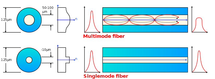
With a longer cable, the light can bounce back and forth more often than with a short one, so the difference gets bigger. In addition, at higher data rates the pulses are
shorter and they follow each other faster. That is why you are more likely to suffer from this phenomenon with longer cables and higher speeds. A signal that has become unusable due to mode dispersion cannot be 'repaired' anymore.
LASER
LEDs are sometimes used for short distances and lower speeds (because of the lower price), but for longer distances you need a LASER. LASERs are better for this application, because a single colour of light can be focused into 1 beam. With other light sources you get a 'rainbow effect', because they do not consist of 1 colour. Because the receiving end cannot distinguish between the different colours, this causes the pulses - just like with mode dispersion - to merge at higher speeds and/or longer distances.
Chromatic dispersion
LASERs are often said to emit monochrome light: light in a single colour. That is not really true. Since LASERs are not perfect, what comes out is not a completely pure colour. And that's a problem: the speed of light through glass fiber is not merely lower than in a vacuum, the 'delay' is also dependent on the wavelength (the colour) of the light. This means that if you 'shoot' a pulse of white light into a very long fiber, you will see the colors of the rainbow at the end of it. This phenomenon is called chromatic dispersion.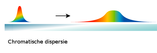
A nice characteristic of chromatic dispersion, different compared to mode dispersion, is that it is reversible. The details of this are too complex for this blog as this will only occur at great distances (say
100km).
Different types of optics
In switches and routers, the optical interfaces are often designed as a slot into which a pluggable optic (usually SFP or SFP+) can be inserted. These optics are available in different types, which can cover different distances. Depending on this, a certain fiber type is required. Incidentally, the distance stated in the specifications of an optic is only an indication. Ultimately, it is all about whether the signal
reaches the receiving end well (enough).
Link budget
"Well enough" in this context means: Not too much dispersion and sufficient brightness. An optic emits light with a certain strength (expressed in dBm). Suppose the TX (transmitting) side of an optic emits
light with a strength of -8dBm and the RX (receiving) side needs at least -14dBm to 'see' it, you can afford to lose 6dBm along the way. This is referred to as the link budget. If you lose more light, you will
first get errors on the link and if you lose even more light the link will not come up anymore. It is therefore important to ensure that you do not lose more light than the link budget. Ensure that connectors are
clean. A little bit of dust or dirt on a connector can easily provide more attenuation than a few kilometers of fiber. Incidentally, more is not always better in this case. There is an upper limit to the amount of
light; an optic that is intended for 80km can, if used at a much shorter distance, blind or even permanently damage the receiver.
Matching optics and fibers
The different types of optics and different types of fiber must match as we have just established. You can imagine that if a light source in an optic is intended for thick (MMF) fiber, it is not possible to shine
light into a thin (SMF) fiber. And vice versa: If the receiver in an optic is intended for SMF, it will not work with MMF because a large part of the light then ends up outside the light-sensitive part of the
receiver.
Different connectors
But there are different connectors, right? That's correct. Many different connectors have been reviewed over the years. In fact, they have become increasingly compact over the years, but there are also less
obvious differences. For example, with some connectors the end of the fiber is angled to prevent light reflected from the end from entering the fiber again. In addition, the same connector type can be used for
both MMF and SMF. The fact that a connector fits is therefore no guarantee that the combination of fiber and optic will work.
Want to know more about fiber optic connections?
Do you have questions about fiber optic connections or doubts about the suitability of fibers or optics for your application? Please feel free to contact us, we are happy to help you. We are also happy to assist you in case of problems. In addition to cleaning sets, we also have measuring equipment such as OTDR and brightness meters.
By: Alex Bik