
- 02-10-20Deep Dive in the BIT colocation network
- 24-07-20SMF or MMF? And what exactly is dispersion on a glass fiber?
- 01-07-20Network statistics in the BIT Portal: techniques and tools
- 11-12-19Ceph’s Software Designed Storage for all possible storage flavours
- 12-09-19Goodbye old firewalls. Welcome Next-Generation Firewalls!
- 15-11-18Techsession: New access network BIT
- 01-11-18Registration of RPKI information for safer routing
- 25-09-18What is 2FA and how can you secure your account with it?
- 10-07-18BIT's new access network
- 13-03-18DNS Amplification Attacks
Deep Dive in the BIT colocation network
02-10-2020 13:47:48

In a previous blog I explained how we at BIT are working on replacing the entire colocation network with a new setup based on equipment from Arista Networks. In this blog post I'll go into more details about the technique behind this setup. A lot has changed compared to the old network.
Topology of the old network
The old network was designed many years ago on the basis of principles and techniques that were current at the time; a core/aggregation/access model that uses the Spanning Tree Protocol (STP). Over the years, the network has been expanded and renewed regularly, but not much has changed in terms of design over the years.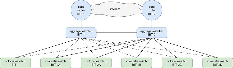
The above diagram shows the old access network schematically. As can be seen here, there are two core routers that access the network via two aggregation switches. The colocation switches are linked to these aggregation switches. Each server room has one or two switches to connect customers and BIT's own equipment, and each of these switches is connected to both aggregation switches for redundancy purposes.
The spanning tree protocol is used between the aggregation switches and the colocation switches to ensure that the network remains loop-free. It is not desirable that, when ethernet frames are generated with an unknown destination, they are infinitely flooded through the network. A network must be loop-free in the switching layer. The spanning tree protocol takes care of that.
However, there are some drawbacks to spanning tree implementations:
- The speed at which traffic is diverted when changes to the network topology occur, for example due to a connection failure, is relatively low. This means that in such situations there can be noticeable
inconvenience for customers. - A topology based on spanning tree is vulnerable. If the CPU load on one of the switches is too high or if one of the connections is overloaded, a loop can occur in the network, because a switch cannot
check fast enough that the loop is present and therefore opens a blocked port correctly. - In order to connect customers redundantly, the spanning tree equipment must participate in the BIT spanning tree topology. This means a lot of fine-tuning in terms of configuration and a greater risk of
problems.
Topology of the new network
The new access network is based on the so-called spine/leaf model, sometimes also called the Clos model. At first glance, the topology is very similar to the double star design used in the old network.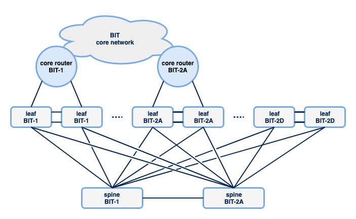
In the spine/leaf model there are a large number of leaf switches that are used to connect equipment. For BIT this means that a number of these leafs have been placed per server room. Ranging from two to (currently) eight leafs, depending on the number of switch ports required to connect BIT customers and equipment. Spine switches are used to enable traffic between these leaf switches. In our network there are two spine switches, placed in BIT-1 and BIT-2A. This creates a double star structure so that switches can reach each other via a maximum of one other switch, namely a spine switch. Each switch has four connections to transport traffic to other parts of the network. As shown in the previous blog post, these connections are redundant and switching to other paths in the event of failure takes place very quickly, because other protocols are used to choose paths between the switches. I will tell you more about this later.
Spine/leaf setups are not necessarily limited to two spines. It is therefore possible that a third and possibly a fourth spine will eventually be introduced as our network grows. In that case, each leaf
switch only needs to be connected to two spines, so you can continue to grow without the need for spine switches that have enough switch ports available to connect every leaf in the network.
The connections to the core routers (and thus the connections to the internet) are placed on different leaf switches. In this respect, the topology differs from the old topology, in which the aggregation
switches transport both the traffic between the access switches and to the core routers. Compared to the old network model, there are also more connections to the core routers. The advantage of this is that there is more capacity and more redundancy.
If you connect the connections to your core network to the switches that handle the high volume of traffic, you can limit the amount of traffic that transports within your access network. In the traditional model
that was used in the old network, the aggregation switches must have sufficient capacity to transport all traffic from the entire access network to the core routers. This creates a kind of funnel effect, where
you need more and more capacity on your aggregation switches as your access network grows.
Routing instead of switching
The new design is built on the premise that we want to route traffic, not switch. The disadvantage of switching is that loop protection is required, as, for example, is done with the spanning tree described
above. That is why we use VXLAN. This is a technique where ethernet frames are encapsulated in UDP datagrams. These datagrams are then routed to the correct destination within the network, where they are
decapsulated again, bringing the original ethernet frame to the destination. Simply put, we route ethernet through IP tunnels. As a result, our network is completely transparent to layer 2 protocols such
as spanning tree, CDP and LLDP. Customers can therefore simply use all these protocols throughout the BIT network. They are transported by our equipment and ignored.
Each switch has several, in our case usually four, routes to destinations in the network (and the internet) and in its route table. These routes are all equivalent and thanks to ECMP (Equal Cost Multi
Path) routing they can all be used at the same time. If a connection is lost, the routes over this connection are removed from the routing table and the traffic will follow one of the remaining routes.
With VXLAN you solve the problem that you have to keep your network loop free. However a new challenge arises: you still have to know to which switch the encapsulated ethernet frame should be routed. And that can also be ports on multiple switches, because for broadcasts and unknown unicast traffic, for example, the frame must be forwarded to all other switch ports that are configured in the same VLAN. So some form of information exchange is needed to keep track of which MAC address and IP address is present on which switch. This can be done through static configurations, for example, but in a network such as that of BIT this is impossible. The list is too big and too fluid due to customers connecting and replacing equipment.
There are also other ways to exchange this information. At BIT we use EVPN for this. EVPN is an extension to the BGP routing protocol that makes it possible to exchange information about MAC addresses and IP addresses. The advantage of BGP is that it is a dynamic protocol that can scale well. In addition, it is an open standard, the protocol has been around for a long time and is known to network engineers. This
makes it more reliable and easier to implement.
When a new device is connected or when a virtual machine moves to another hypervisor, the presence of the MAC address on a switch is communicated via EVPN to all switches in the access network. Our network no longer suffers from ARP and CAM timeouts. Changes are immediately propagated to all switches.
By combining VXLAN and EVPN, two networks are actually created, called the underlay and the overlay. The underlay connects the switches and ensures that ethernet frames are encapsulated and decapsulated. The overlay is the network that is built over it. This is the network into which customer traffic is routed and which is the visible network to the outside world.
VXLAN and EVPN are open standards. This makes it possible to use equipment from other brands in the future and to allow other types of equipment to participate in the setup. For example, we have already
conducted tests to unlock hypervisors via VXLAN. That makes unlocking virtual machines and virtual networks even easier.
New possibilities with VXLAN and EVPN
The use of VXLAN and EVPN, and the more general use of Arista software and hardware, offers us a number of new opportunities that benefit ourselves and our customers. Below I will list some of them.
Multi-Chassis Link Aggregation Group
One of the new possibilities is the support of Multi-Chassis Link Aggregation Group (MC-LAG). Multiple connections, originating at different switches, are bundled into one logical connection. If one of
the switches from the MC-LAG fails, you will lose capacity, but the connection will continue to work.
A limitation of MC-LAG is that it can only be implemented on pre-selected pairs of switches. At BIT we have chosen to always make pairs of two switches that are located in the same server room. Of
course, procedures at BIT are designed in such a way that activities (such as software updates or changes) are never carried out simultaneously on switches that together form a pair.
For a customer to be able to use MC-LAG, the switch to which the connections to BIT end up must also support MC-LAG (in the case the connections on the customer side are also decoupled on different switches).
Redundancy through the use of vARP
The MC-LAG as just described can be used to redundantly connect customer switches (or possibly servers that support port channelling) to a set of BIT switches. However, many customers connect their network through a router or firewall. And it also often happens that a customer has equipment in different server rooms, so that redundant connection to an MC-LAG pair is only possible by making connections to an MC-LAG pair in one server room. The additional consequence is that equipment in another server room will also depend on the availability of the room where the MC-LAG pair is located. That does not benefit the availability.
Fortunately, there are more ways to connect customers redundantly. The way we use most often is called "vARP" (Virtual Address Resolution Protocol). One unique virtual gateway IP address is offered on all ports of a customer. That gateway is active on all these ports at the same time. Every switch (or actually: router) from BIT thus becomes a gateway for the customer network, which ensures that routing is optimal. Customer devices in this IP network always grab the gateway of the switch they are connected to. The use of vARP makes it easier for us to connect a customer network in different places to our network, where for the customer it is just one network in which he has one gateway and in which his machines can also communicate with each other. In the overlay it therefore appears to be a simple network for the customer, while in the underlay with VXLAN, EVPN and vARP it is ensured that traffic ends on the correct ports of the correct switches in the spine / leaf setup.
Automation
Arista's software offers many possibilities for automation. For example, Ansible is supported to manage and roll out configurations, and there are options to communicate with switches via an API. With the libraries that Arista offers, it is easy to collect information from switches. We use this, among other things, for monitoring and troubleshooting of the switches, but we can also use this to enable customers to gain more insight into the status of their switch ports via the BIT Portal.
The complete configuration of all switches is managed through Ansible. Ansible makes it possible to standardise configurations via play books, a type of recipe, whereby only one set of the configuration variables
specific to that customer, such as which switch port of which switch a customer is connected, needs to be supplied. This prevents mistakes when making configurations. Via Ansible it is also possible to subsequently roll out these configurations to switches.
The Ansible configurations and playbooks used are managed via Gitlab, a version control package. This makes accountability (who changed what and when) possible. BIT uses a four-eyes principle for changes, which is enforced by Gitlab. We also use "CI / CD pipelines" in Gitlab. These are scripts that check proposed changes in various ways for any errors before they can be accepted and rolled out.
Data visualization through streaming telemetry
The new Arista switches support streaming telemetry, which means that we have much more different and, above all, much faster measured values available compared to the old network. This gives a better picture of the status of the network and can provide a swifter and more detailed insight in the event of problems.
In a recent blog post I explained the tools and techniques we use to make the streaming telemetry data produced by the switches accessible to customers through our portal.
Want to know more about our colocation network?
We are of course very enthusiastic about this new setup and would like to share our knowledge with you. If you want to know more, you can contact us via info@bit.nl or via +31 318 648 688.
By: Teun Vink